
Wind Turbine Blade Design
The optimal design of wind turbine blades must meet several sometimes conflicting goals, such as maximizing annual power output, minimizing vibration and avoiding resonance, reducing material consumption, ensuring structural stability, and meeting appropriate strength and stiffness requirements.
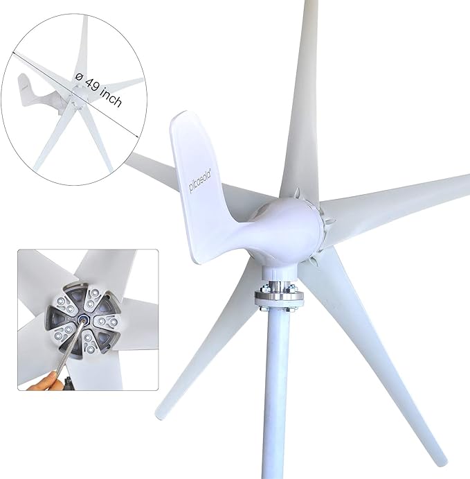
Pikasola Wind Turbine Generator Kit 400W 12V with 5 Blade, Wind Generator Kit with Charge Controller, Wind Power generator for Marine, RV, Home, Windmill Generator Suit for Hybrid Solar Wind System, Check The Price >>>
Design Stages
The design of wind turbine blades can be divided into two main stages: aerodynamic design and structural design. Aerodynamic design focuses on maximizing power output and minimizing vibration, while structural design emphasizes reducing material consumption, ensuring stability, and meeting strength and stiffness requirements. These stages are iterative, ensuring that blade thickness is sufficient to accommodate the web and enhance blade stiffness.
Shape Design
The aerodynamic design of the blade involves optimizing its shape, a critical aspect that directly affects power generation efficiency. Under typical operating conditions, the blades operate at low Reynolds numbers and high lift coefficients. The design of the blade profile is therefore crucial. Modern blade design often utilizes advanced aircraft wing airfoil design methods and CFD technology to analyze and optimize aerodynamic shapes.
Historically, wind turbine blades used NACA series aviation airfoils, such as NACA44XX, NACA23XX, and NACA63XX. However, these airfoils are sensitive to leading edge roughness, leading to significant performance losses when contaminated. Recognizing this, the development of specialized airfoils for wind turbine blades began in the mid-1980s. Notable examples include the Seri and NREL series in the United States, the RISO-A series in Denmark, the FFA-W series in Sweden, and the DU series in the Netherlands.
These specialized airfoils offer various advantages: the Seri series has low sensitivity to surface roughness, the RISO-A series performs well near stall conditions, and the FFA-W series excels in rear stall performance. The Danish LM company, for example, uses the Swedish FFA-W airfoil in large wind turbine blades.
Several design theories for blade shape exist, primarily based on wing aerodynamic theory. Early methods, like the simplified design method based on the Bates theory, assumed optimal conditions without considering eddy current loss, resulting in efficiency not exceeding 40%. Later, more sophisticated theories emerged, such as the Schmitz theory, which considers blade circumferential vortex loss, and the Glauert theory, which accounts for vortex flow behind the rotor but ignores blade airfoil resistance and blade loss. Wilson’s improvements on Glauert’s theory included blade loss and lift-to-drag ratio considerations, making it the most commonly used design theory today.
Structural Design
Modern large-scale wind turbine blades typically use a skin-main beam structure. The skin, reinforced by biaxial composite layers, provides the aerodynamic shape and bears most shear loads. The trailing edge cavity uses a sandwich structure to enhance stability, similar to automotive applications. The main beam, reinforced with unidirectional composite material layers, serves as the primary load-bearing structure, while the web, also a sandwich structure, supports the main beam.
Blade structure design involves checking the structural layers using general commercial finite element software, such as ANSYS, NASTRAN, and ABAQUS. The ultimate strength, natural vibration frequency, and blade tip deflection are critical considerations. Compared to other structures, the hollow sandwich structure of current large-scale blades offers high resistance to buckling instability and high natural vibration frequency, resulting in relatively lightweight designs. The design process involves iterative steps, updating analysis models, and adjusting ply schemes to meet design criteria. Due to the orthotropic properties of composite materials, strain failure criteria are often used for blade structure checks.
Material Selection
Initially, wind turbine blades were made from various materials, including wood, cloth, steel, and aluminum. However, as blade sizes increased, composite materials, particularly fiberglass reinforced plastic (FRP), became the preferred choice due to their design flexibility and ability to meet strength and stiffness requirements. FRP remains dominant in large fan blades due to its low cost and excellent performance. As blade sizes increase, incorporating high-strength fibers like carbon fiber in high-stress areas becomes necessary to meet the stringent requirements of large-scale and lightweight blades. The bending-torsion coupling design concept, inspired by aviation applications, is used to control aero-elastic deformation, reducing blade fatigue loads and optimizing power output.
Blade Length
The length of wind turbine blades depends on the design power and wind farm conditions. Generally, higher power requires longer blades. In wind farms with lower average annual wind speeds, longer blades are also necessary. Blade manufacturers continuously optimize blade structures to achieve cost-effectiveness across different wind farms. The specific shape of a high-performing blade involves complex processes in fluid mechanics and aerodynamics.