
CNC Lathe Operation Panel
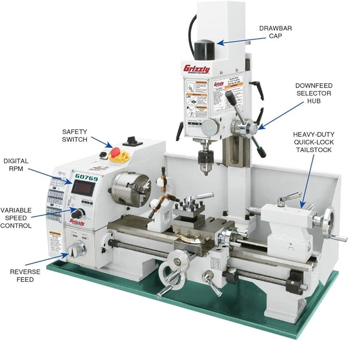
Grizzly Industrial G0769-8″ x 16″ Variable-Speed Combination Lathe/Mill, Check The Price >>>
The CNC lathe operation panel is composed of several key components that allow the operator to interact with the CNC system effectively. Below are the primary elements and their functions:
1. Display Device
The CNC lathe’s display provides vital information to the operator, depending on the system’s status and the operation commands. This may include:
- The program being edited or currently running.
- The machine’s machining state.
- The command and actual coordinate values of the machine tool axes.
- Graphic simulations of machining paths.
- Fault alarm signals.
Basic display units may feature only a few digital indicators for character display, limiting the information presented. Advanced display systems offer richer, more comprehensive information.
2. NC Keyboard
The NC keyboard consists of the MDI keyboard and soft function keys:
- MDI Keyboard: Includes standardized letters, numbers, and symbols (some accessed via the shift key). This keyboard is mainly used for editing part programs, inputting parameters, MDI operations, and system management.
- Function Keys: Primarily used for navigating and operating system menus.
3. Machine Tool Operation Panel (MCP)
The MCP integrates all the system’s control buttons, often referred to as the button station. These buttons directly control the machine’s operations, such as:
- Starting and pausing the part program.
- Manually feeding the coordinate axes.
- Adjusting feed speed.
4. Handheld Unit
While not essential, some CNC lathes include a handheld unit to provide additional convenience. The handheld unit typically includes:
- A manual pulse generator (MPG).
- A coordinate axis selection switch.
It is particularly useful for controlling manual feed and axis movement.
Interpretation of CNC Lathe Operation Panel Keys
The following is a brief overview of the basic functions and uses of the keys on a CNC lathe operation panel, using the FANUC and Guangshu systems as examples:
Keys Starting with the Letter “A”
- ABS (Absolute Coordinates): Displays the current absolute X and Z axis positions on the screen.
- ALL (Comprehensive Coordinates): Displays both absolute (X, Z) and relative (U, W) axis positions.
- ALTER: Modifies or replaces characters in the program.
- AUTO: Automatic operation mode where the machine processes commands automatically.
- AUXGRAPH: Activates the graphic display function.
Keys Starting with the Letter “C”
- CAN: Cancels input characters or symbols.
- CHECK: Activates the soft key for viewing.
- CURSOR: Moves the cursor on the screen for editing.
Keys Starting with the Letter “D”
- DELETE: Deletes characters or symbols in the program.
- DGNOSPARAM: Accesses parameter settings and displays diagnostic data.
Keys Starting with the Letter “E”
- EDIT: Enters the editing mode for programming or modifying data.
- EOB: Inputs a semicolon “;” symbol.
Keys Starting with the Letter “F”
- FWD: Commands the spindle to rotate forward.
Keys Starting with the Letter “H”
- HELP: Accesses help or assistance.
- HEDSS: Activates the handwheel.
Keys Starting with the Letter “I”
- INPUT: Used for inputting parameters, offset values, or command data in MDI mode.
- INSERT: Inserts a character or symbol after the cursor.
Keys Starting with the Letter “J”
- JOG: Activates manual operation mode, allowing manual control of the machine.
Keys Starting with the Letter “L”
- LIB: Displays machine memory content.
- LOCK: Controls a specific operation switch.
Keys Starting with the Letter “M”
- MAC-LOCK: Media access control lock.
- MDI: Manual data entry mode.
- MEM: Accesses memory files.
- MENUOFSET: Used for setting and displaying offset values.
Keys Starting with the Letter “O”
- OFS/SET: Similar to the “MENUOFSET” key, used for offset value settings.
- ONPUTSTART: Executes the input command to an I/O device.
Keys Starting with the Letter “P”
- PAGE: Scrolls forward or backward on the display.
- POS: Displays the current machine tool position.
- PROG: Displays the memory content of the program.
Keys Starting with the Letter “R”
- RAPTDTRAV: Commands rapid movement in manual mode.
- REL: Displays the current relative U and W axis positions.
- RESET: Resets the CNC system, cancels alarms, or stops the machine mid-operation.
Keys Starting with the Letter “S”
- SHFT: Selects characters or functions on multi-character keys.
- SING: Step-by-step manual jog mode for controlled processing.
Keys Starting with the Letter “W”
- WORK: Sets the workpiece coordinates.
Keys Starting with the Letter “Z”
- ZSN: Returns machine coordinates to zero.
Speed Override Keys
CNC lathes generally have three types of speed override keys:
- Spindle Speed Override: Adjusts the spindle speed based on operational requirements.
- G00 Rapid Override: Controls rapid movement speed during G00 commands.
- Cutting Speed Override: Adjusts the cutting speed as needed.