
Working Principle and Wiring of a Flash Relay
Working Principle of the Flash Relay
A flash relay is an automatic control device that activates when the input quantity (electricity, magnetism, sound, light, or heat) reaches a predetermined value. When this set value is reached, the output changes, causing the relay to “jump.”
The relay’s characteristics can be described as follows: when the input signal xx increases continuously from zero to the action value xxx_x, the armature starts to pull in, and the output signal of the relay immediately jumps from y=0y = 0 to y=ymy = y_m. This means the normally open contact changes from off to on. Once the contact is closed, if the input quantity xx continues to increase, the output signal yy will no longer change. When the input quantity xx drops from a value greater than xxx_x to xfx_f, the relay starts to release, and the normally open contact disconnects. This characteristic is called the relay characteristic, also known as the input-output characteristic of the relay. The ratio of the release value xfx_f to the action value xxx_x is called the feedback coefficient.
How to Wire a Flash Relay
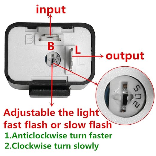
To wire a flash relay:
- L is connected to the light.
- B is connected to the power supply.
- E is connected to the ground.
Types of Flash Relays
There are three types of flash relays commonly used in automobiles:
- Capacitive flasher
- Wing flasher
- Electronic flasher
Pin Definitions for Flash Relays
The three pins of the flasher are defined as follows:
- B: Power terminal, connected to the power supply (+)
- L: Flasher control terminal, connected to the lamp (+), and the lamp (-) is connected to the ground
- E: Ground terminal, connected to the vehicle body and the power supply (-)
Working Principle of the Electronic Flasher
The electronic flasher uses the switching characteristics of a transistor, along with the charging and discharging delay characteristics of a capacitor, to control the on and off states of the relay coil. This, in turn, connects and disconnects the contacts, causing the turn signal lights to flash.
Electronic flashers are widely used in automotive turn signal systems due to their reliable operation and long service life. They are available in contact and non-contact types, integrated circuits, and transistors.
Detailed Circuit Description
The three pins of the electronic flasher are:
- B: Power terminal
- L: Flasher control terminal
- E: Ground terminal
The charging circuit involves:
- The battery’s positive power switch (SW) terminal BB
- Emitter ee
- Base bb
- Capacitor CC
- Resistor R3R3
- Terminal SS
- Turn signal light KK
- Right turn signal lights
- Ground (battery negative)
When the car turns to the right:
- Turn on the power switch SWSW and the turn signal switch KK.
- The current is supplied by the battery’s positive pole to terminal BB, resistor R1R1, and the normally closed contact JJ of the relay.
- Terminal SS, turn signal switch KK, and right turn signal grounding complete the loop, causing the right turn signal to light up.
As the current passes through resistor R1R1, a voltage drop occurs, turning on the transistor VTVT due to forward bias. The collector current passes through the relay coil JJ, causing the normally closed contact of the relay to open, turning off the right turn signal light.
When the transistor VV is on, the base current charges capacitor CC. As the capacitor charges, the charging current decreases, and the collector current IcI_c of the transistor also decreases, causing the relay contacts to close again, turning the turn signal lights on. The capacitor CC then discharges through resistor R2R2, the normally closed contact JJ of the relay, and resistor R3R3. The voltage drop generated by the discharge current on R2R2 provides a reverse bias voltage for the transistor, accelerating its cutoff. When the discharge current is close to zero, the voltage drop across R1R1 provides a forward bias for the transistor to turn on again.
This continuous charging and discharging of the capacitor, along with the switching of the transistor, causes the relay contacts to repeatedly open and close, making the turn signal flash.