Heat Transfer Coefficient of a Heat Exchanger
The heat transfer coefficient of a heat exchanger measures the effectiveness of heat transfer between fluids. It varies depending on factors like flow rates, viscosity, and the presence of fouling materials. The approximate range of the heat transfer coefficient (K-value) in various types of heat exchangers is as follows:
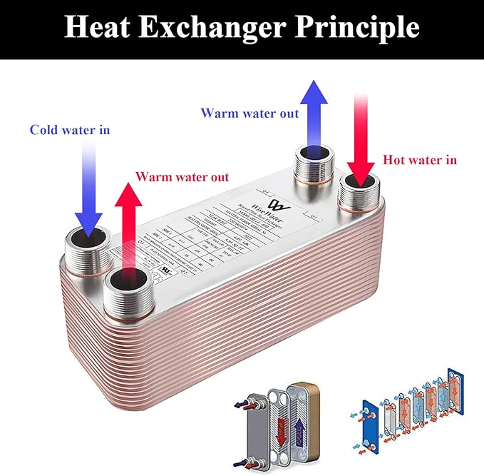
- General range: 1800~2200 W/m²·℃
- Tube heat exchangers: 800~1000 W/m²·℃
- Spiral plate heat exchangers (water-water): 1000~2000 W/m²·℃
- Plate heat exchangers (water-steam to water): 3000~5000 W/m²·℃
Calculation of the Heat Transfer Coefficient
In air-conditioning engineering, for single-layer heat exchangers, the heat transfer coefficient (K-value) can be calculated without considering additional thermal resistances, as follows:
K=1(1h1+δλ+1h2) W/(m2⋅°C)K = \frac{1}{\left(\frac{1}{h_1} + \frac{\delta}{\lambda} + \frac{1}{h_2}\right)} \, W/(m²·°C)
Where:
- h1,h2h_1, h_2: Heat exchange coefficients of both surfaces of the envelope (W/m²·°C)
- δ\delta: Thickness of the pipe wall (m)
- λ\lambda: Thermal conductivity of the pipe wall (W/m·°C)
Thermal Resistance and Conductivity Calculations
- Thermal Resistance of a Single-layer Structure
R=δλ (m2⋅K/W)R = \frac{\delta}{\lambda} \, (m²·K/W)
Where:- δ\delta: Thickness of the material layer (m)
- λ\lambda: Thermal conductivity of the material [W/(m·K)]
- Thermal Resistance of a Multilayer Structure
R=R1+R2+⋯+Rn=δ1λ1+δ2λ2+⋯+δnλnR = R_1 + R_2 + \cdots + R_n = \frac{\delta_1}{\lambda_1} + \frac{\delta_2}{\lambda_2} + \cdots + \frac{\delta_n}{\lambda_n}
Where:- R1,R2,⋯ ,RnR_1, R_2, \cdots, R_n: Thermal resistance of each material layer (m²·K/W)
- δ1,δ2,⋯ ,δn\delta_1, \delta_2, \cdots, \delta_n: Thickness of each material layer (m)
- λ1,λ2,⋯ ,λn\lambda_1, \lambda_2, \cdots, \lambda_n: Thermal conductivity of each material [W/(m·K)]
- Convective Heat Transfer Resistance
- Inner surface: Ri=1h1R_i = \frac{1}{h_1}
- Outer surface: Re=1h2R_e = \frac{1}{h_2}
- Total Heat Transfer Resistance
R0=Ri+R+ReR_0 = R_i + R + R_e
Where:- RiR_i: Inner surface heat transfer resistance (typically 0.11 m²·K/W)
- ReR_e: Outer surface heat transfer resistance (typically 0.04 m²·K/W)
- RR: Thermal resistance of the structure (m²·K/W)
- Heat Transfer Coefficient of the Building Envelope
K=1R0 W/(m2⋅K)K = \frac{1}{R_0} \, W/(m²·K)
Where:- R0R_0: Total heat transfer resistance of the envelope structure
Heat Transfer Coefficient for Doors and Windows
- Average Heat Transfer Coefficient of an Outer Wall
Km=KpFp+Kb1Fb1+Kb2Fb2+Kb3Fb3Fp+Fb1+Fb2+Fb3K_m = \frac{K_pF_p + K_{b1}F_{b1} + K_{b2}F_{b2} + K_{b3}F_{b3}}{F_p + F_{b1} + F_{b2} + F_{b3}}
Where:- KmK_m: Average heat transfer coefficient of the outer wall (W/m²·K)
- KpK_p: Heat transfer coefficient of the main part of the wall (W/m²·K)
- Kb1,Kb2,Kb3K_{b1}, K_{b2}, K_{b3}: Heat transfer coefficients of the thermal bridges around the wall (W/m²·K)
- FpF_p: Area of the main wall (m²)
- Fb1,Fb2,Fb3F_{b1}, F_{b2}, F_{b3}: Areas of the thermal bridges (m²)
- Heat Transfer Coefficient of Aluminum Alloy Doors and Windows
Uw=AfUf+AgUg+LgΨgAf+AgU_w = \frac{A_fU_f + A_gU_g + L_g\Psi_g}{A_f + A_g}
Where:- UwU_w: Heat transfer coefficient of the window (W/m²·K)
- UgU_g: Heat transfer coefficient of the glass (W/m²·K)
- AgA_g: Area of the glass (m²)
- UfU_f: Heat transfer coefficient of the frame (W/m²·K)
- AfA_f: Area of the frame (m²)
- LgL_g: Perimeter of the glass (m)
- Ψg\Psi_g: Linear heat transfer coefficient around the glass (W/m²·K)