
UPS Power Supply System
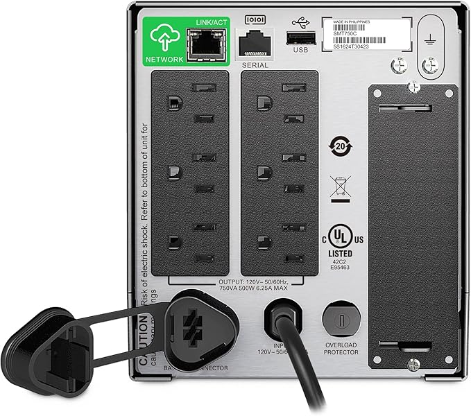
A UPS power supply system consists of four main components: rectification, energy storage, conversion, and switch control. The system’s voltage regulation function is typically performed by a rectifier. This rectifier uses a silicon-controlled rectifier or a high-frequency switching rectifier, allowing it to adjust the output amplitude in response to changes in external power. As long as these external power fluctuations remain within acceptable limits, the system maintains a rectified voltage with a nearly constant amplitude.
The purification function is handled by the energy storage battery. Since the rectifier cannot completely eliminate transient pulse interference, the rectified voltage may still contain interference pulses. The energy storage battery, in addition to storing direct current energy, acts like a large capacitor connected to the rectifier. Its equivalent capacitance is proportional to the battery’s storage capacity.
Because the voltage across a capacitor cannot change abruptly, the battery’s smoothing characteristic helps eliminate pulse interference, serving a purification role—also referred to as shielding interference. Frequency stabilization is performed by the converter, and the stability of the frequency depends on the converter’s oscillation frequency. For ease of operation and maintenance, the UPS power system includes various switches: a system work switch, an automatic bypass switch for self-check faults, and a maintenance bypass switch.
When the grid voltage operates normally, it powers the load while simultaneously charging the energy storage battery. In the event of a sudden power failure, the UPS system kicks in, and the battery supplies power to maintain normal operations. If the load increases due to production needs, the grid voltage is rectified to supply power directly to the load.
Working Principle of UPS Power Supply
- AC-DC Conversion: Grid-supplied AC power is stepped down, full-wave rectified, and filtered into DC voltage using an autotransformer, which then supplies power to the inverter circuit. The AC-DC input includes a soft-start circuit to prevent impact on the grid when switched on.
- DC-AC Inverter Circuit: A high-power IGBT module full-bridge inverter circuit, with a large power margin, ensures low output impedance across a wide dynamic range and fast response characteristics. High-frequency modulation and current-limiting technology, combined with rapid short-circuit protection, allow the inverter to operate safely and reliably despite supply voltage transients, load shocks, or short circuits.
- Control Drive: The control drive manages the entire system’s functions. It provides detection, protection, synchronization, and drives various switches and display signals. It also performs SPWM (sinusoidal pulse width modulation) control, improving the inverter’s dynamic characteristics and stability through static and dynamic dual voltage feedback.
UPS Power Supply Operating Process
When mains power is at 380Vac, the DC voltage in the main circuit supplies the DC-AC inverter, producing a stable 220Vac output, while simultaneously charging the battery. If the mains voltage drops or there is a sudden power loss, the battery provides power to the DC circuit via an isolation diode switch. The switch to battery power is seamless, with no interruption. When the battery is nearly depleted, the UPS system emits an audible and visual alarm, halts inverter operation at the lower discharge limit, and signals a prolonged alarm.
The UPS also features overload protection. In case of a moderate overload (150% load), it switches to bypass mode and automatically reverts to normal operation once the load stabilizes. For severe overloads (over 200% of the rated load), the system immediately stops the inverter output and enters bypass mode, potentially tripping the front air switch. After resolving the fault, restarting the system is as simple as resetting the switch.
To ensure proper operation and avoid overload or underload, calculate the load capacity before powering on the UPS. For an FR-UK type UPS (nominal rated power), the design load capacity is 80% of the resistive load. When used with a typical computer load, the system follows this formula:
∑i=1 n Pi ≤ P
Where:
- P is the output capacity of the UPS (VA), and
- Pi is the volt-ampere of the i-th load.
Examples of power consumption:
- Each PLC power: 220V * 0.5A = 110VA
- Each workstation: 220V * 2A = 440VA
- IBM PC client and server: 220V * 1.5A = 330VA
Total power consumption for the production line:
- 10 * 110VA + 4 * 440VA + 11 * 330VA = 6,790VA
- 6,790VA / 0.8 = 8,112VA
Thus, a 10KVA UPS is suitable for this production line.