Types and Wiring Methods for Three-Phase Four-Wire Electricity Meters
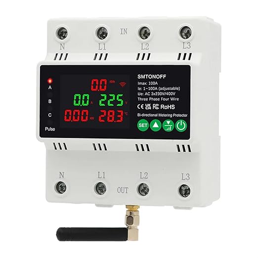
Electricity meters come in various wiring configurations, including single-phase and three-phase connections, as well as direct connection types and those using current and voltage transformers. Among these, the three-phase meter typically measures the total power consumption across three live wires, each carrying a voltage of 380V. The three-phase meter is available in two main types: three-phase three-wire and three-phase four-wire meters. In this article, we will explain how to wire a three-phase four-wire meter and how transformers are involved in the process.
Wiring Diagram for a Three-Phase Four-Wire Electricity Meter
Electricity meter wiring generally follows two primary circuits: voltage circuit and current circuit. The current coil connects in series with the load, or to the secondary side of the current transformer, while the voltage coil is wired in parallel with the load, or to the secondary side of the voltage transformer.
A three-phase four-wire active meter is equipped with three driving components and typically features 11 terminals. These meters are commonly used in hybrid power circuits that supply both power and lighting. Below are two wiring configurations for a three-phase four-wire meter:
1. Direct Connection of Three-Phase Four-Wire Meter
In this setup, nine terminals are connected to the load, the neutral line is linked to the 10th terminal, and the 11th terminal connects to the opposite end of the load.
2. Connection via Current Transformer
In this configuration, the live wires (U, V, W) are connected to the primary terminals (L1) of the current transformer, while the secondary side of the transformer connects to the watt-hour meter (terminals 1, 4, and 7). Note that the L1 connection must have its connecting piece removed for safety, and the secondary side’s terminal (K2) should be grounded.
Understanding the Three-Phase Four-Wire Line System
The three-phase four-wire system consists of three phase wires (A, B, C) and a neutral line (N), also referred to as the zero line. This system is designed to derive a 220V line-to-neutral voltage from the 380V three-phase supply. Additionally, the neutral line may be used to detect zero-sequence currents, ensuring a balanced three-phase power supply. The color coding for wires in this system is typically as follows:
- A Wire: Yellow
- B Wire: Blue
- C Wire: Red
- N Wire: Brown
- PE (Protective Earth) Wire: Yellow-Green
Types of Electrical Wiring Systems
Single-Phase Wiring Systems:
- Single-phase two-wire: 1 live wire + 1 neutral wire.
- Single-phase three-wire: 1 live wire + 1 neutral wire + 1 ground wire.
Three-Phase Wiring Systems:
- Three-phase four-wire: 3 live wires + 1 neutral wire.
- Three-phase five-wire: 3 live wires + 1 neutral wire + 1 ground wire.
Why Use a Transformer in a Three-Phase Meter?
Transformers are often added when the meter needs to handle currents exceeding 100A. By stepping down the current before it enters the meter, the transformer protects the meter from potential damage caused by high current. When a transformer is used, the reading from the meter must be multiplied by the transformer’s ratio to get the accurate consumption.
The Three-Phase Four-Wire System (TN-C System)
In a three-phase four-wire system (TN-C system), the neutral point of the transformer is grounded. Both the protection neutral line (PE) and the working neutral line (N) are shared, forming a PEN line. This system is suitable for balanced three-phase loads but may pose safety risks if the load is unbalanced.
Issues with the TN-C System:
- Unbalanced Load: An unbalanced load can create an unbalanced current in the PEN line, which could lead to hazardous voltage on the neutral line.
- Leakage Protection: If a leakage protection switch is used, it should only be connected to the working neutral line and not the protection neutral line.
- Grounding Safety: Repeated grounding is essential to reduce neutral-to-ground voltage, ensuring safety. However, improper grounding can result in electric shock risks or unstable voltage references.
Transition to the TN-S System:
The TN-S system addresses these issues by completely separating the neutral and protective ground lines. This method is more reliable, especially in situations where the load is unbalanced, and is now the preferred system for modern electrical installations.
Conclusion
Understanding the wiring methods for three-phase electricity meters is crucial for proper installation and maintenance. The three-phase four-wire system, whether connected directly or through a transformer, offers flexibility and safety when correctly configured. Additionally, the distinction between single-phase and three-phase wiring systems is important for both residential and industrial power setups. Always ensure correct wiring and grounding practices to prevent safety hazards and ensure efficient power distribution.